Posts

Showing posts from July, 2017

Week 8 - Spartan Superway Internship (Final Week)

Image
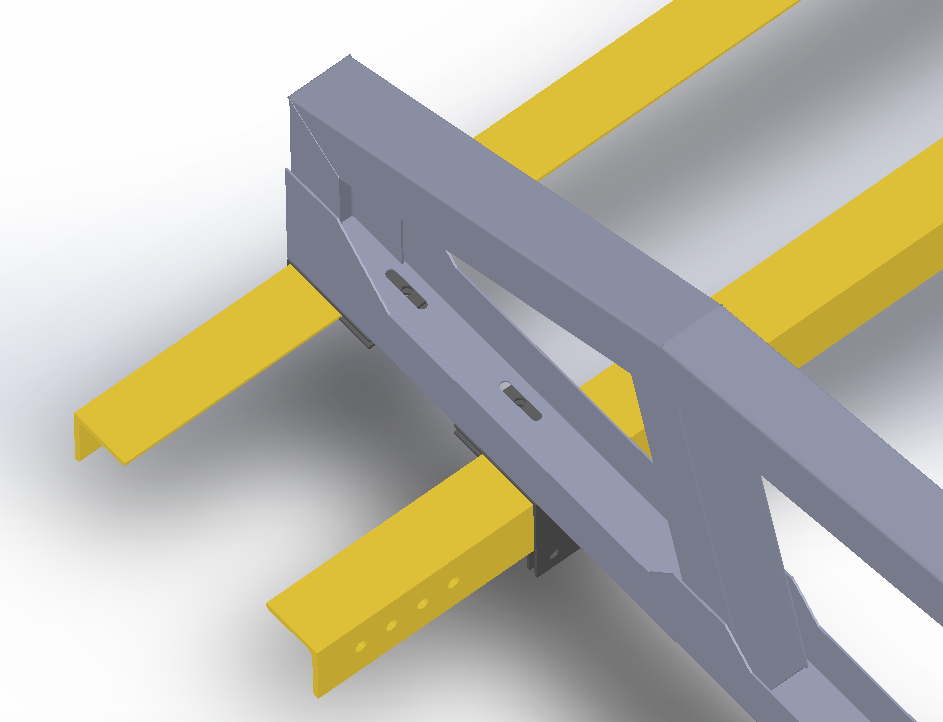
With the last week of my Spartan Superway internship, I began to make final revisions to my design. We plan to send the design out to a manufacturing company, where they will cut our design out of sheet metal and fold it for us. It will take approximately 3 weeks for its production, so by the start of Fall 2017, those working on the Spartan Superway for their senior project will be able to assemble it. The first step I did was to revise the top and bottom L brackets that attach the mount to the L beams of the track. I made them smaller to accommodate the new design, but still being able to slide them along the the tracks for adjustability.  Figure 1: Revised brackets with mount and beams With the widened track, I also extended the bolt slots of the bottom of the mounts to reach the 3.5 meter distance between the two tracks. Lastly, I added bolt holes to the frame to allow the braces and the top and bottom pieces to be connected. Unfortunately since we do not know which pan

Week 7 - Spartan Superway Internship

Image
During our seventh week of the internship, I began improving on our mount design. With the previous design, the dimensions of the new track were not taken into account. Now that I have received a general idea of what the new layout will be like, I have made the necessary changes to accommodate this rack onto the rail system. The first step was to widen the holes. We learned that the new tracks are now 3.5 meters apart from center to center, so I needed to spread the mounting holes more. In addition, a new beam will be attached to the top, so I have raised the whole array in order to not cause any problems with spacing. Lastly, I widened the flanges in order to be more stable. Until I do any finite element analysis, I will not know how much of a change this makes, however I believe that it should help a bit.    Figure 1:  Assembled mount Below the upper and lower pieces of the mount have been flattened to show how it will be cut from sheet metal. A goal we are trying to a

Week 6 - Spartan Superway Internship

Image
During week 6, I began to revise my second mount design. Instead of creating a new design, I decided to add onto a previous concept that I was provided. Because I did not know the resources we had available for processing the sheet metal into parts, I believed it would be best to work off of a previous concept that one of the mentors worked with and has knowledge of the tools available. The design first begins with two upper and lower pieces that are made from sheet metal and will be connected with bolts at each end. In order to support the middle parts of the upper mount, I designed it to add braces made of sheet metal to support and downward forces that may act upon it. You will see in figure 2 that bolt mounts have been extended off the piece. Figure 1: Upper mount piece Figure 2: Lower mount piece Figure 3: Upper and lower assembled With the upper and lower assembled, I added simple braces made from sheet metal to support the middle sections. These braces a